
Inside College Road: Engineering the Modules of One of the World’s Tallest Modular Buildings

Michael Hough is the Director of MJH Structural Engineers.
The Missed Opportunity in Modular Design
College Road is a groundbreaking residential development in East Croydon, South London by offsite developer and contractor, Tide, its modular company Vision Volumetric (VV), and engineered by MJH Structural Engineers. The scheme comprises two of the world’s tallest modular buildings delivering almost 1000 new homes. A 35-storey tower provides 120 affordable homes, and a 50-storey tower provides 817 co-living homes, one of the largest co-living developments across the globe. Both have significant amenity spaces and a double level basement. Fundamentally, this development was delivered on a constrained 2,000 m2 site in only 28 months from start to finish due to its modular delivery. The towers were constructed using 1725 Vision modules wrapping two concrete cores, placed on a four-storey concrete transfer structure, containing amenity facilities for the building.
System Description
This project was designed by MJH, Tide, Vision, and HTA architects with a modular solution in mind from the outset maximising the system abilities at an early stage to ensure efficiencies. The flexibility of the Vision system allows the full floor plate outside of the central core to be constructed as individual interconnected room enclosing modules.
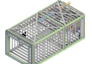
Each module is manufactured from a series of wall panels, a floor and ceiling. The wall panels are assembled with steel frames welded between the main structural members. These walls are engineered to provide the structure for the final building with considerations for the temporary stages of construction. The walls need to be strong and stiff enough for the handling, moving and resulting forces that occur before full assembly into 3D modules.
Once assembled into modules the lifting and handling must consider the stiffness of the assembled components and prevent distortions. A concrete floor is poured in the factory and adds stiffness and weight to the module.
Design and Loads
Each concrete slab is engineered for the specific module based on span and openings with local details to transfer connection forces into the concrete slab. In the permanent position the slabs only have tension on the lower surface, but tension may occur on the upper surface in the temporary stages. If a module overhangs a truck bed, then the slabs may need to cantilever either to the side or off the back of the trailer. With modular construction the design loading and situation may not always arise on site or in the completed building.
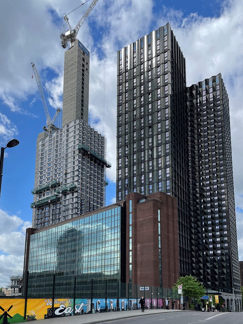
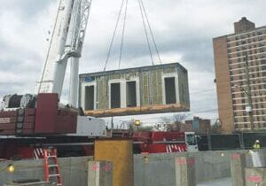
A photo of College Road, left, under construction. Photo: Michael Hough.
The critical forces on various members within a modular system occur at different times. Modular walls, particularly internal to the building perimeter, are sheltered from load in their permanent location. The design case may be the wind due to transportation or during placing on site where they are exposed. On the trailer there may be pressures and suctions generated from the speed that far exceed those experienced-on site.
For the College Road height of construction, we use wind tunnel assessments that identify the wind pressures and suctions. These are mainly used to inform the stability design but may provide local forces also.
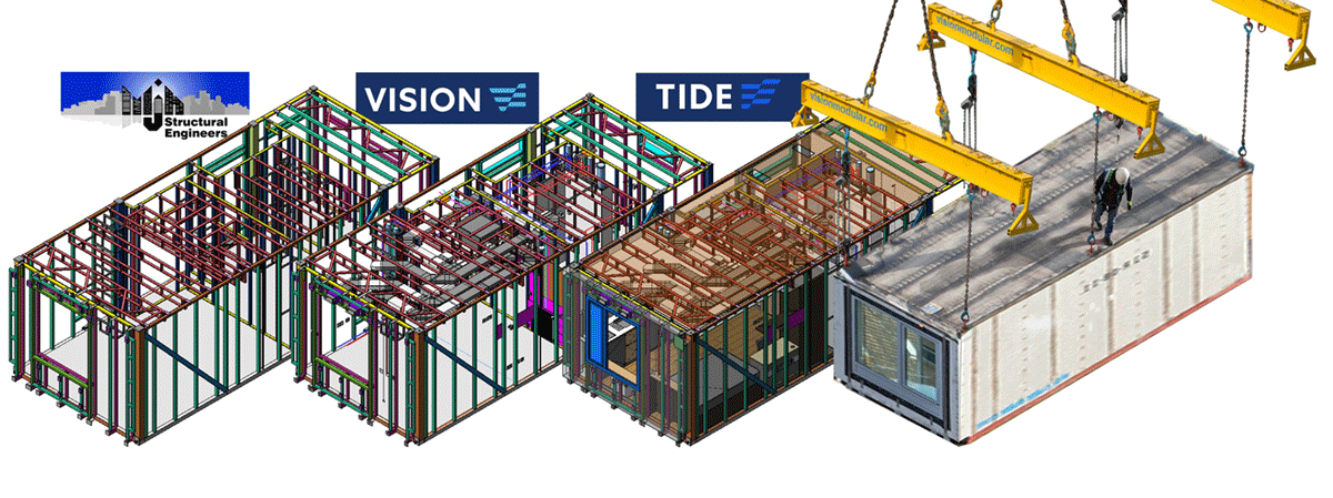
The design vertical loads vary throughout the height of the building and are assessed by way of detailed structural modelling. MJH’s design considers each column by storey individually so each column in each position in the building is engineered to be efficient. This is essential to manage the steel tonnage in tall construction. The analysis forces are taken from the building model and considered together with other design considerations outside of standard engineering design programs as these do not consider all the requirements for modular design. Designed sizes are added back to the model and an iterative design process results in compatible design and analysis sizes.
There is a complex distribution of load in modular construction related to the stiffness of the floor and wall construction which is influenced by the stiffness of the floor in particular. Further effects occur in tall structures where the stiffness of the foundation and transfer structure may influence the distribution of axial load through the building. To further investigate the efficiencies in the design we undertake staged construction analysis of the building as the modules are placed level by level. This allows an understanding of the connection forces, that arise as the modules are placed, and the loading conditions change.
There are various elements of the module that are engineered for their intended use, and which do not vary significantly throughout a building. The ceiling supporting members have a reasonably standardised design base on their span, the load conditions do not vary by story or by room. These members support the internal finishes, services, external finishes for the temporary transportation and placing stages and need to be stiff and strong enough to allow personnel access during the placing operation. It is likely that site access will dictate the design of these members as this will be the highest loading and any brittle finishes will be in place, so the deflections need to be restricted. Similar design requirements occur for infill studs in walls where they do not form a main element of the engineered completed structure.
There are many items in a modular system that may be designed to reach a certain level of capacity that is mostly sufficient and requires minimal further assessment. Where capacities are exceeded then additional solutions are required for these areas. Determining the most efficient construction to meet the majority of requirements is essential to efficient manufacture.
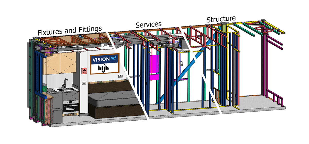
Automation and Manufacturing
Vision set up their modular system and the manufacturing process to encompass as broad a range of sizes and shapes as they possibly could. This allows greater architectural freedom in maximising the modular content of a development but also if utilised to a high level can put pressure on the delivery of the system throughout the design, detailing, procurement and manufacture.
Over the years in MJH we have worked to add levels of automation into our workflows through computational engineering and coding. Standardisation within the system is at a component level, where we build the modules from elements that are well understood into modules that vary significantly. Automation in the design and detailing stages allows reductions in the critical path time leading to manufacture especially where there are large numbers of variations in modular layouts on a floor plan.
Complex Loads
DfMA is a powerful tool — but only when wielded in service of Lean flow. The modular industry can’t afford to treat design and manufacturing as separate domains. When they’re integrated, factories hum, projects deliver on time, and customers get exactly what they were promised.
If we want modular construction to fulfill its potential, we must move beyond designing for assembly and start designing for flow. That means embedding flow principles in the earliest design conversations, empowering production teams to shape those designs, and viewing every product through the lens of factory fit and sequencing.
The future of modular isn’t just smarter design — it’s synchronized design. And that begins with DfMA that flows.
Fire
Fire considerations in taller modular construction falls outside of the practical area of previous fires, thankfully we do not have experience of real fires in modular buildings. As a result, there are additional assessment criteria to assess the consequences of high temperatures in one area of a building adjacent to another where ambient temperature prevails. In traditional construction structural members are more likely to be shared between these areas but in modular construction, whether good or bad, the structure is mostly separated either side of a compartment wall.
Extreme temperatures will try to expand structural members such as columns and this expansion is resisted by the building weight, the connectivity to other elements of structure and the adjacent strength of cooler members. Thermomechanical models are created and analysed for all our modular buildings to assess the movements and forces, and these are based on fire tests of full modules, walls, floor assemblies and components and on stiffnesses generated in tests both digital and physical. These assessments do not change our overall building designs and layouts for the Vision system but offer high levels of confidence in this form of construction due to the extreme temperatures used in the modelling beyond what is practically achievable in buildings.
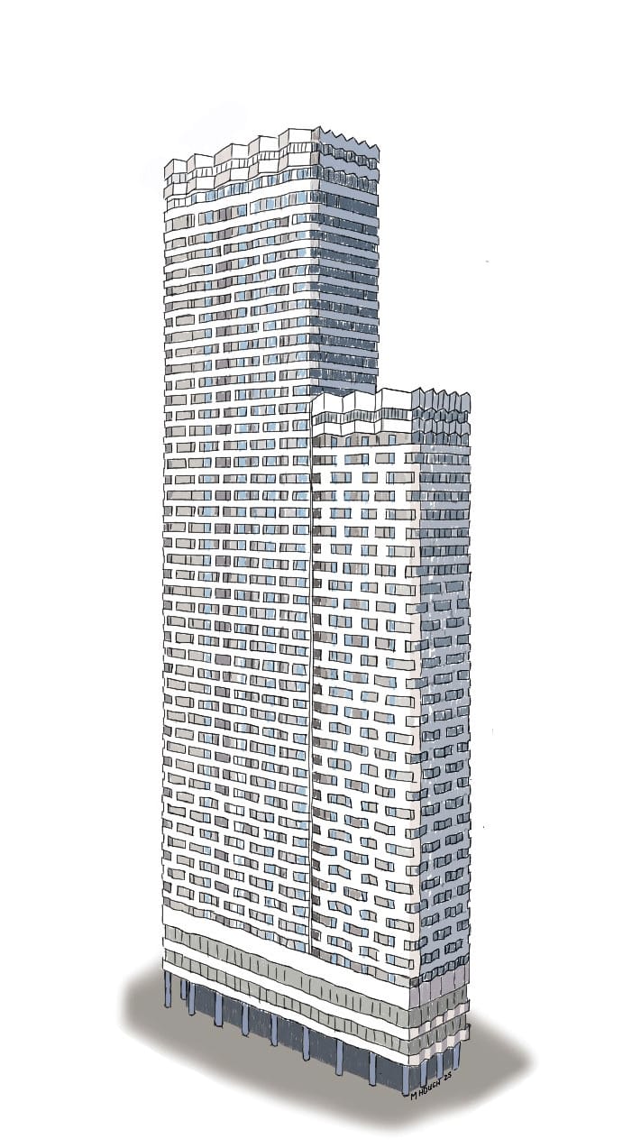
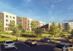
An exterior sketch of College Road.
Collaboration
A key enabler of this design flexibility and efficiency is the close collaboration between MJH, Vision, and our fabrication partners. The full structural model is developed in Tekla Structures and shared in real time with our steel fabricator, allowing fabrication details to be coordinated directly from a live, centralised model. This open exchange of information removes silos and ensures all parties are working to the latest design data. In parallel, Vision models and coordinates all architectural and MEP elements within Autodesk Revit, which is continuously aligned with the structural model to identify and resolve potential clashes ahead of manufacture.
This integrated digital workflow, underpinned by robust BIM coordination, ensured a high level of precision and consistency across the supply chain throughout the delivery of the College Road project.
More from Modular Advantage

MBI Town Halls 2026: Reflections from Boston
By the end of 2026 MBI’s Government Affairs team will have traveled over 6,000 air miles to bring Town Hall events to five different cities in two countries.
Mind the Gap: The Interface Between Onsite and Offsite Construction
Every design for manufacture and assembly (DfMA) project — modular, mass timber, or panelized — is really two projects joined at a seam. One is built in a controlled factory to millimeter tolerances; the other in the field, in weather, to the looser tolerances of poured concrete and human hands. Between them sits an interface: where the factory’s precision meets the site’s reality.
Rules, Rails & Repeatability: Applying DfMA to Modular Healthcare
DfMA offers several advantages for healthcare projects, with faster delivery among the most valuable. Schedule matters when building new facilities, expanding campuses, renovating existing space or bringing care closer to communities that need it.
Precision and Possibility: Demands of DfMA and What Modular Mass Timber Makes Possible
Mass timber does not automatically create an efficient modular building. Its precision makes early coordination more important: fabricated components will accurately reproduce both the team’s solutions and its mistakes. The material’s advantages are realized only when supported by an equally precise design and delivery process.
Catch It in the Factory, Not in the Field: Smarter Testing for Modular Builds
Integrating watertightness and airtightness testing into factory workflows transforms quality assurance from a reactive process into a proactive commissioning strategy. It ensures that every module shipped is field ready and resilient for transportation while also supporting the ability of the modular construction industry to make buildings better.
Modular Construction Contracts: Key Considerations for Successful Canadian Projects
Starting a modular project with a well-developed contract protects both the owner and the contractor. It will help keep the project on track and on budget, and it will improve quality from the factory floor to final installation on-site.
Modular by Design: Turning Architecture into a Manufacturing System
Modular construction is often presented as a faster way to build. Speed, however, is only one part of its value. The larger opportunity is to create a coordinated design and production system that improves quality, reduces uncertainty, and allows a building to move efficiently from concept design through manufacturing, transportation, installation, and completion.
Repeatability Begins with Trust: What Alora at Dry Creek Reveals About Scaling Modular Housing
Alora at Dry Creek, a 329-unit, multifamily community comprising five four-story buildings in Centennial, Colorado, demonstrates how repeatable design, standardized manufacturing and early collaboration can work together to create a model that is not only faster to deliver, but easier to replicate across future projects.

T.R. Arnold: The Art of Third-Party Inspections
T.R. Arnold (TRA), a third-party inspection company in Elkhart, Indiana, contracts with modular manufacturers across the US. Manufacturers register with each state to which they intend to send their modules and may be required to hire a third-party inspection company.

Creating an ‘Ecosystem for Innovation:’ 50+ Years of Modular Construction Oversight in Virginia
Virginia’s modular building program began in 1973, with the implementation of the Virginia Industrialized Building Unit and Mobile Home Safety Regulations. Now it’s leading the country in modular code adoption.